
LT1021 的數據手冊實在是寶貝,這篇文章解讀里面的參考漂移如何影響系統精度,以及如何通過 TRIM 引腳微微修正。
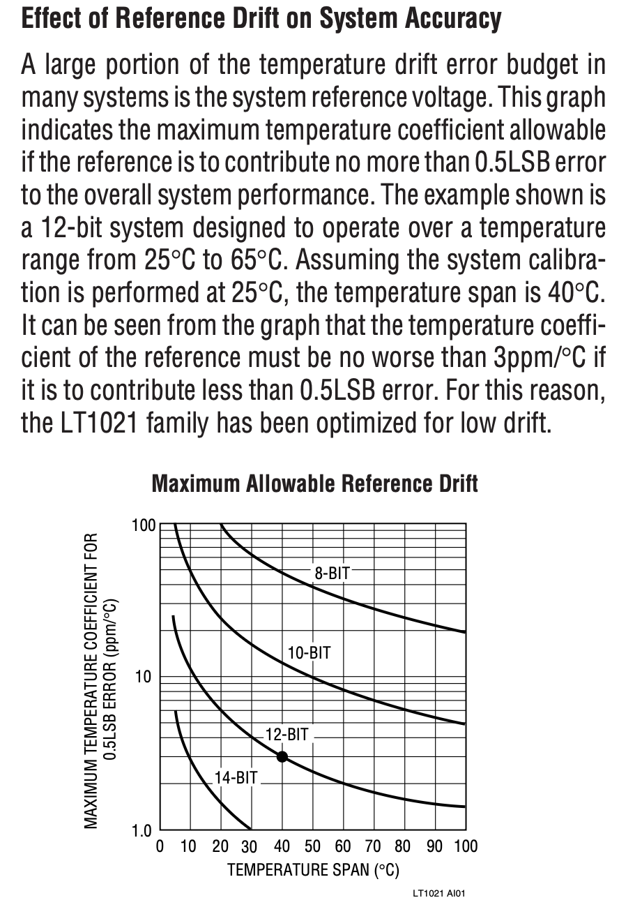
A large portion of the temperature drift error budget in many systems is the system reference voltage.
在很多系統中,溫度漂移誤差預算里最大的一塊,往往來自“參考電壓”本身;不是 ADC、不是放大器、不是算法,而是 Vref。(這個結論是比較出乎常理的)
This graph indicates the maximum temperature coefficient allowable if the reference is to contribute no more than 0.5 LSB error to the overall system performance.
關鍵點:0.5 LSB 規則
圖不是隨便畫的,它基于一個系統級容許原則:參考源的溫漂,只允許占系統誤差的 0.5 LSB。為什么是 0.5 LSB?因為超過 0.5 LSB,系統就會出現碼跳變/非單調風險
The example shown is a 12-bit system designed to operate over a temperature range from 25°C to 65°C.
設定條件:
12-bit 系統
校準在 25°C
工作到 65°C→ ΔT = 40°C
It can be seen from the graph that the temperature coefficient of the reference must be no worse than 3ppm/°C if it is to contribute less than 0.5LSB error.
這是整頁最重要的一句話。
12-bit → 1 LSB = FS / 4096,0.5 LSB = FS / 8192 ≈ 122 ppm(滿量程),ΔT = 40°C
所以允許的 TC 上限:
這不是經驗值,是嚴格預算推出來的。
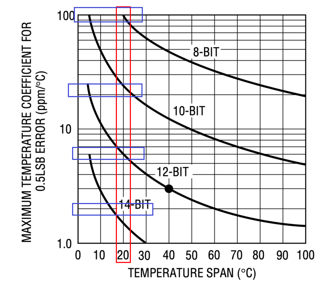
圖的縱軸:
Maximum Temperature Coefficient for 0.5 LSB Error (ppm/°C)
橫軸:
Temperature Span (°C)
不同曲線:8-bit,10-bit,12-bit,14-bit
分辨率每提高 2 bit,允許的參考 TC 大約就要再降低一半到四分之一
換句話說:
| <0.3 ppm/°C(幾乎不可能靠裸基準做到) |
這張圖在邏輯上已經證明:只靠“選一個好基準”是不夠的,必須引入補償或控溫。
比如我現在的目標是:10 V 基準,只有十 μV 級漂移→ 1 ppm 級
這意味著什么?即便是 LT1021-10B(2–5 ppm/°C),在 ±10°C 內→ 也必然超預算。所以:這張圖不是在“評價 LT1021 好不好”,而是在告訴我們;系統精度已經逼著工程師必須做溫度補償。
10V 版本的修調:能用,但要克制
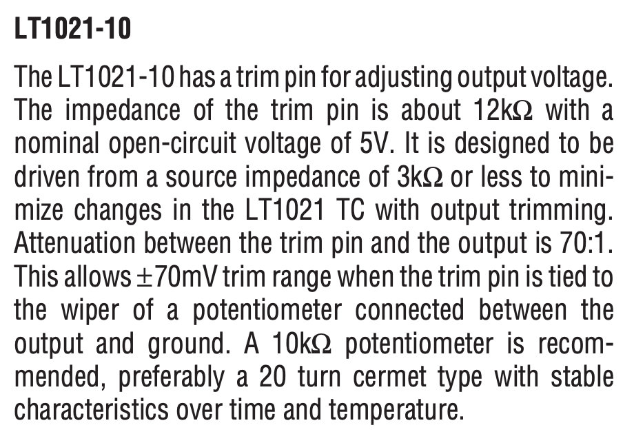
Trim 引腳等效阻抗:≈12 kΩ
開路等效電壓:≈5 V
Trim → 輸出的衰減:70:1
推薦驅動源阻抗:≤3 kΩ
Trim 實際是在內部參考網絡的一個高阻節點,外部源阻抗、噪聲、溫漂→ 都會被耦合進核心
這就是為什么 datasheet 強調:
to minimize changes in the LT1021 TC with output trimming
This allows ±70mV trim range…
這對“調到整數值”很方便,但大幅 trim 會顯著拉高 TC,所以 后面立刻給了一個更聰明的做法(C 級)
The LT1021-10 “C” version is pre-trimmed to ±5mV and therefore can utilize a restricted trim range.
這里說的不是“B 級 / C 級精度”,而是 工廠已經幫你把絕對值拉到 ±5 mV 內。
然后:
*A 75k resistor in series with a 20kΩ potentiometer will give ±10mV trim range.*Effect on the output TC will be only 1ppm/°C for the ±5mV trim needed…
Trim 本身不可怕,可怕的是“無限自由的 trim”。在小范圍 trim(±5~10 mV)內調整應該嚴格限制源阻抗,使用穩定的多圈 cermet→ TC 代價 ≈ +1 ppm/°C
這一段看起來在講 5V 版本,但它的“邏輯價值”非常高。
Trim 引腳 TC:?1.7 mV/°C
輸入阻抗:≈100 kΩ
Trim → 輸出衰減:13:1
然后一句非常重要的話:
For the voltage trimming not to affect reference output TC, the external trim voltage must track the voltage on the trim pin.
如果給 trim 的電壓“溫度行為”和內部節點不一致,就相當于把一個新的 TC 注入進系統了。
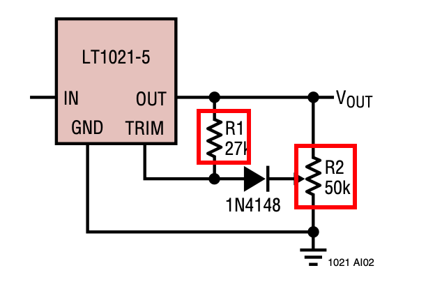
這就是為什么他們推薦:特定的 R1/R2 比值,特定的拓撲:并明確說:
so the exact values shown should be used
讀到這里我知道了所有 trim 本質上都是“模擬注入”,必須為它的溫度行為負責。
The 7V version of the LT1021 has no trim pin because the internal architecture does not have a point which could be driven conveniently…
這句話其實是在“泄露架構信息”:不是每個版本都能安全地“插手內部基準”,有些版本根本不允許模擬 trim。
但即便如此:
the output of the LT1021 can be loaded with a trim potentiometer
也就是說我們仍然可以在外部做調整,但這已經是“系統級手段”,不是芯片級。
一旦精度要求高到一定程度,修調一定會上移到系統層(數字/算法/架構),而不是停留在芯片引腳上。


